Wiring outlets safely
Having electrical outlets over open water is risky, and if you can do anything to reduce that risk, I think it's worth it. Water can make contact a variety of ways: A pump squirting upward, a big splash when you drop something or when livestock decides to jump, or even during something mundane like a waterchange and the hose accidentally floods our outlets as you move it from point A to point B. On top of that, salty air occurs around the clock due to evaporation, and when the climate calls for it, condensation can occur on and in those outlets. Has any of this struck a chord with you? Think about how your electrical is currenlty set up, and if you know something needs doing, don't delay. Saltwater and electricity often equals fire, and that means loss of life and property.
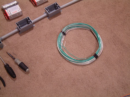
At Home Depot, I purchased waterproof electrical boxes with matching conduit pipe. Waterproof coverplates were an extra expense, but I felt it was a prudent choice. Once this is installed properly, water is very unlikely to get into those boxes. Each box will have a GFCI-protected outlet, so if it gets splashed it will trip to the off position. Each box is wired separately so that the other dry boxes will continue to function when one trips. This project for waterproof boxes easily ran $200 in parts alone, but safety is priceless.
I needed 18' of wiring to reach from the left end of the tank, wrap around the walls of the room to where the power station switches are located. I also wanted to keep things tidy. After talking with the electrician at Home Depot, we decided the best choice was to use individual strands of wire rather than romex. Amazingly, I was able to run 15 wires through a 1/2" pvc pipe.
Each electrical box has a GFCI outlet, and has its own wiring so that I can turn off the power at the American DJ Power Station. If the switch is on the outlet has power and a little LED light shines as a visual indicator. If that switch gets splashed or the equipment causes a short, the GFCI button should trip and cut power immediately to that outlet but nothing else. All other equipment will run as it should.
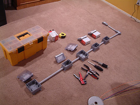
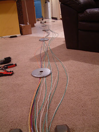
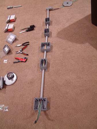
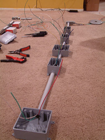
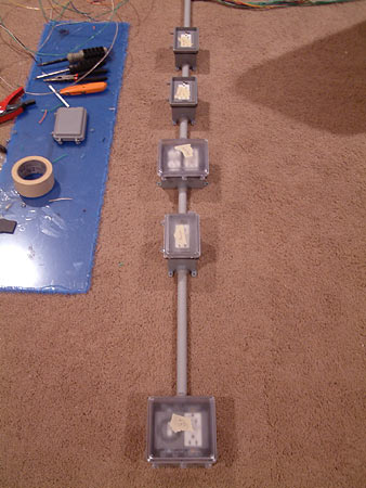
The first thing I did was lay out the new boxes in the configuration I had in mind. Then I had to stretch out the wiring to be able to work with it.
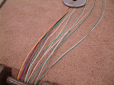
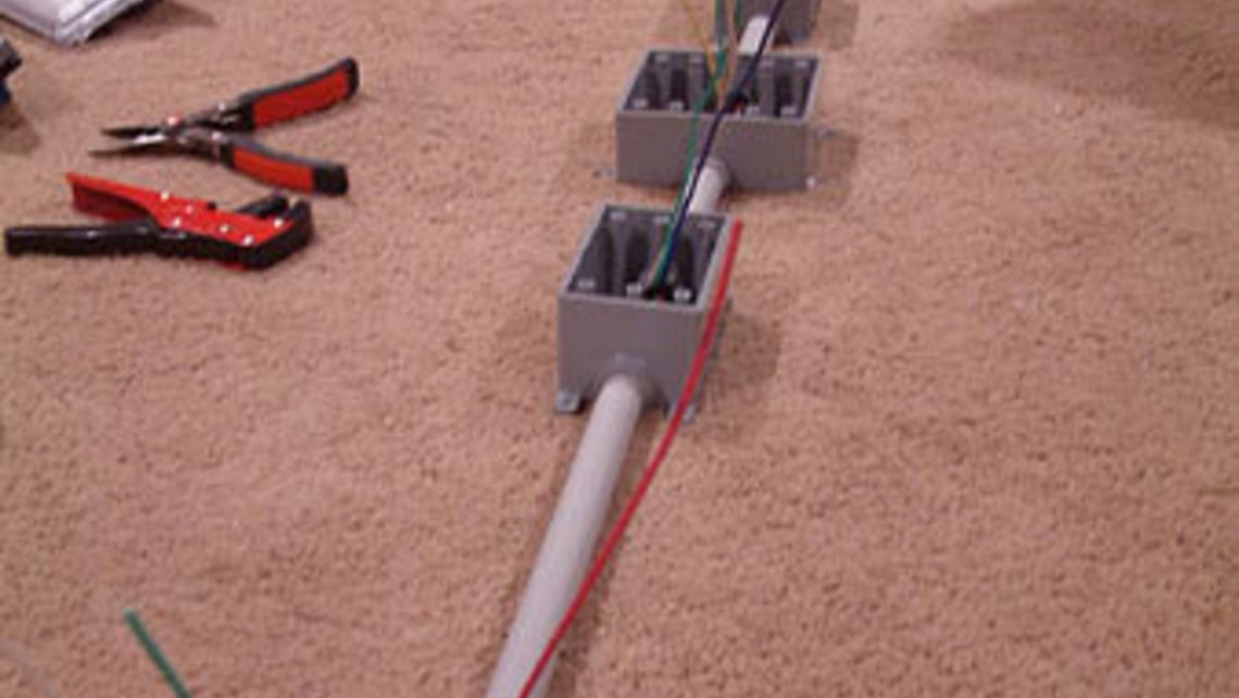
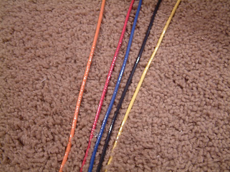
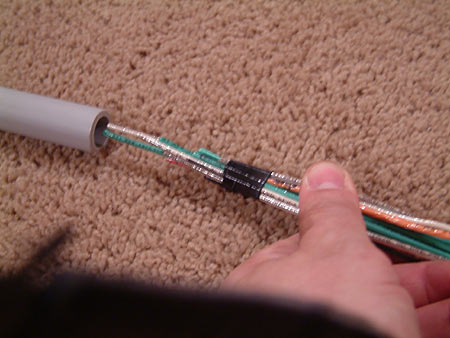
Each box has its own color coded hot lead. Below you can see how the wiring was weighted to keep it relatively straight. Each box gets one green, one white, and one of the five colored leads (which is the hot wire).
The common wire is white and the ground is green as it should be.
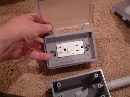
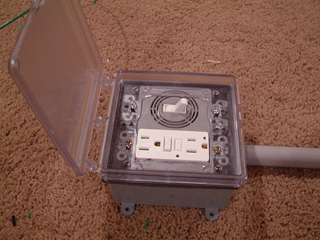
I wanted to see how the boxes would work with the outlets inside. The internal plastic plate can be trimmed to accomodate almost any type of outlet or switch available. This one stated it could be set up 40 different ways. I like the look.
So, onto the wiring. I taped the 15 wires together to make it easier to feed it through the PVC and boxes. This was easier than trying to pull a few at a time. None of the PVC was glued yet.
Once that was done, I pulled out three wires from each box. That was a little tricky figuring out which ones were already taken as I worked my way from box to box.
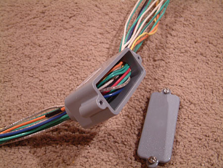
Also, at the end of the chain of boxes, I needed the wires to turn a corner so I used this little device. It gives you access to feed the wires easily, and then a coverplate is screwed over it to keep it water-tight.
All that was left was to wire in each outlet, and screw the top section of the box to the base. Easy, right? It takes some time.
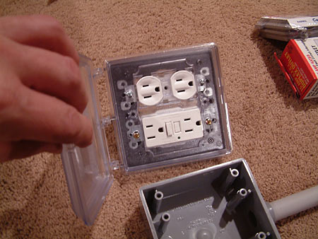
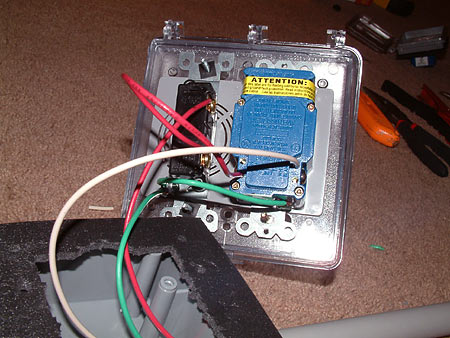
I wanted a couple of plugs handy for water changes, etc. They needed to be GFCI protected, with a simple switch to turn it on and off right at the spot. I really don't like unplugging pumps when my hands are dripping wet, so a switch is quick and safe.

This is how it was wired. The red wire is the hot, the green ground and the white neutral or common. The green and white were screwed into the GFCI outlet, and the red was run to the switch and then from the switch to the GFCI outlet. I also ran the ground to the switch itself, for my own personal peace of mind. When the switch is on, the hot lead provides power to the outlets.
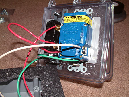
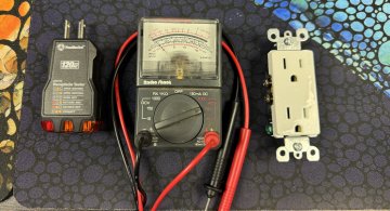
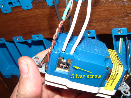
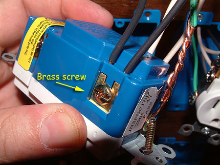
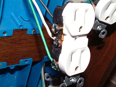
It is very important that outlets are wired correctly to avoid tripping a breaker or crossing power lines. Here are a few pictures how a GFCI outlet should be wired. These may not be exactly the same as what you can buy locally, but the premise should be the same. The reason you see two sets of each wire is because one set goes to the outlet, and the other set continues to the next outlet in series. That way if the GCFI trips, the outlet(s) after it will also be powerless. Remember - silver screw for the white wire, brass screw for the black wire, and green screw goes to the ground wire.
If you only want the first outlet to trip and the next ones to stay powered, continue wiring in this method. If not, please scroll down to learn how to protect all subsequent outlets. In the next three pictures, you'll see two white & two black wires going to the appropriate screws, as well as the ground wires.

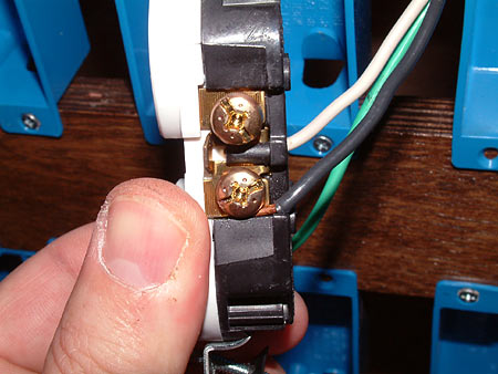
To daisy-chain outlets after a GFCI outlet (making them all turn off when the GFCI trips): Be sure to read the labeling and included instructions.
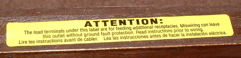
If you plan to run additional boxes after the GFCI outlet, the wires that lead to the next box must be affixed to the LOAD side of the outlet. Click image for larger version
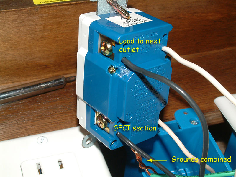
I hope that was clear.
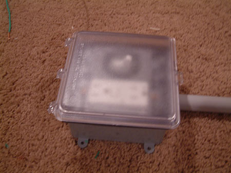
Back to the waterproof boxes. With the cover open, and closed.
The rest of the boxes were simpler, with the appropriate wire going to each screw on the outlet. And once I was done, it looked like this.
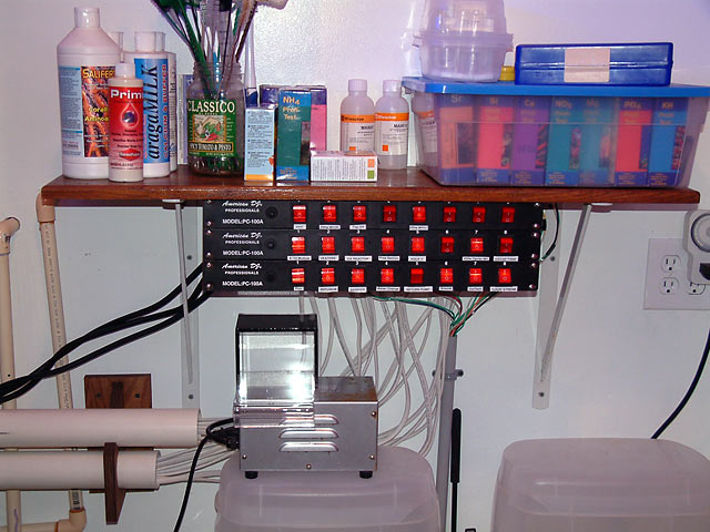
Installed over the sump. All conduit was glued to the boxes with Oatley's CPVC glue, and the conduit was run all the way to the DJ Power Stations where the wires plugged in to matching on/off switches.
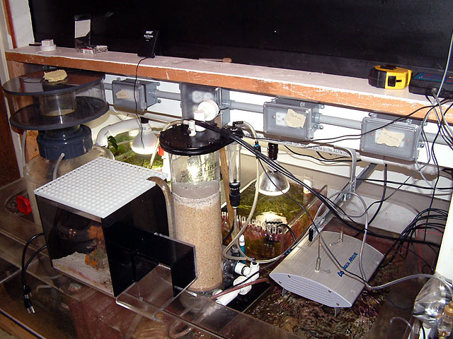
You can see the gray conduit coming up the wall and the colored wiring going up to the American DJs.
How to wire regular outlets
The same priciple applies to regular outlets. These are specifically designed for Copper (Cu) wiring. If your home happens to have aluminum (Al) wiring, you'll need to find the more expensive made-for-aluminum outlets that use special screws to prevent arcing and overheating. My previous older home had aluminum wiring, and instead of $.58 outlets I had to buy $3.24 ones. These would be marked CO-ALR on the back. So here's a regular outlet wired. Click image for larger version.
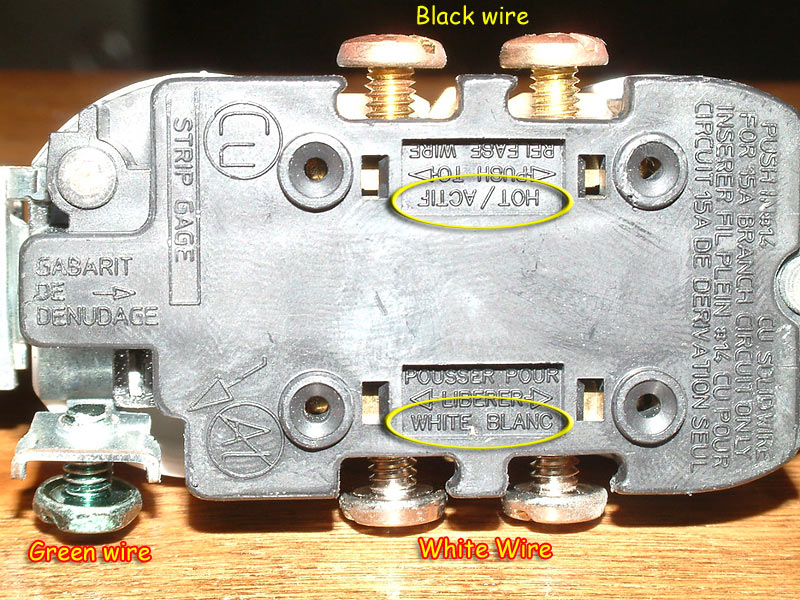
White and green screwed in (top picture). Black screwed in (bottom picture).
Please note I tightened the screws on each wire, instead of the press-in system readily available. I've been told those work but aren't as secure and in my opinion not as safe. Plus due to the fact I'm using shallow boxes, there wouldn't have been any room to press the wires into the holes on the back of each outlet and still fit in the boxes.

With all this information, you are no longer powerless to do a similar project for your reef tank. Happy wiring!
(Standard disclaimer here that I'm not responsible for you making your hair stand on end or for any resulting fireworks. Be safe, test your work and watch what you're doing, or find someone else willing to be your scapegoat.)
Something with HTML textformat