DJ88's DIY calcium reactor
This is a very old page I compiled way back in 2004 to help organize a lengthy thread about a DIY calcium reactor. I'm reposting it because all of the included pictures, but I'm not offering up any other support or answers. This is simply documentation - learn from it, build your own, that's all up to you. :)

The purpose of a Calcium Reactor is to create a constant supply of calcium in the reef environment. Numerous corals and invertebrates use calcium to build their skeletal structure, which depletes this element from the water column. Using a two part solution once a day is an alternative, but on larger setups it is more cost effective and efficient to set up a reactor instead. Below is the latest design I came up with which has worked quite nicely. It is easier to build than typical round reactors, and hopefully you can build one for yourself as well.
This page is not designed to provide you with a model that you can copy for the purpose of reselling. It is intended for a guide for DIY'ers everywhere, to help save them a few dollars and give them the satisfaction of a job well done.
My logic for the design of this reactor is this:
- I wanted to minimize fittings outside the reactor and plumbing. To do this I had to have both fittings come out of the bottom.
- I also wanted to have an upflow reactor. To be able to do this I needed to draw the water in the reactor back down. Without having a stupid amount of piping inside I needed to split the chamber in two.
Easiest way to do this is exactly that. Split it in two. Doing this with a circular chamber would be a bit tricky to ensure a strong bond of all the acrylic inside. So I went and bought $25 worth of pre-cut arcylic and made it square. It turns out I had twice as much as I needed.
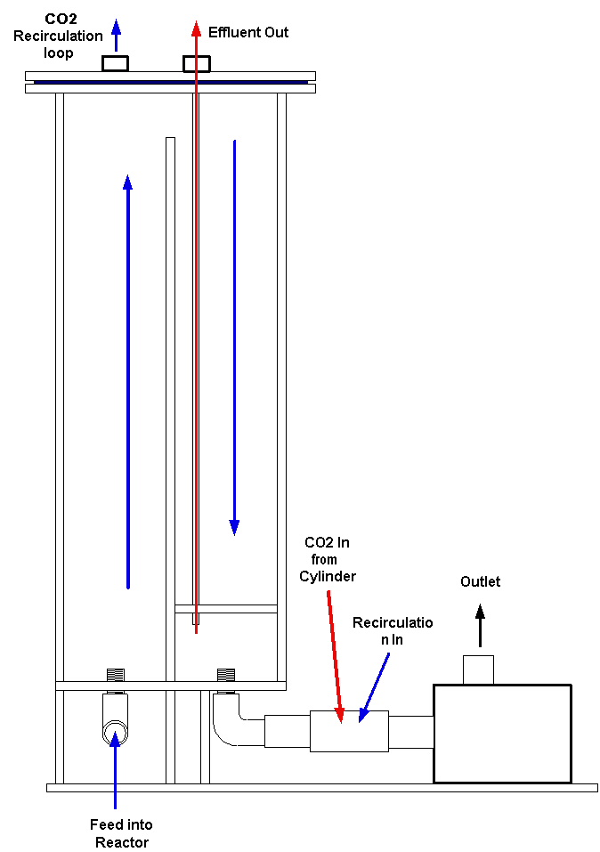
In one half of the reactor the water is forced up through the media and then passes over the divider and then back down to the outlet and circulation pump. The downflow area should trap any possible bits of media that were broken apart and would then possibly be sent out of the reactor as particles. Thus giving the benefits of BOTH styles of reactors currently used. To make sure that I am sending the "cleanest" possible effluent out I have built in a small diameter acrylic tube inside the downflow side to just above the outlet to the circ pump. A piece of poly tubing is then fed down to the void space between the foam and the outlet which is used as the effluent out to the tank.
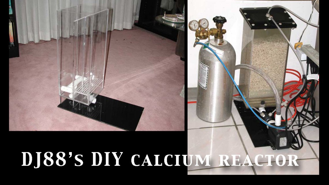
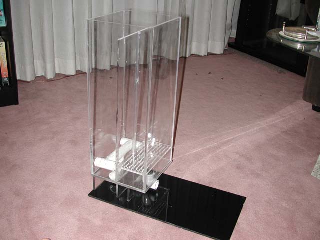
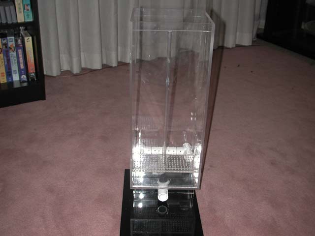
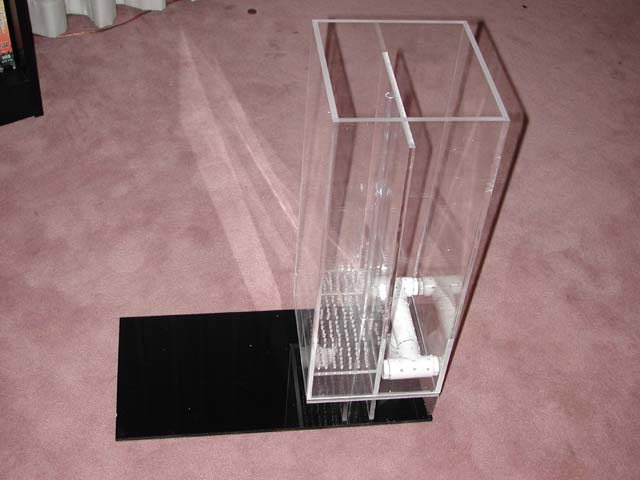
Below are pictures from several angles to help you visualize the construction.
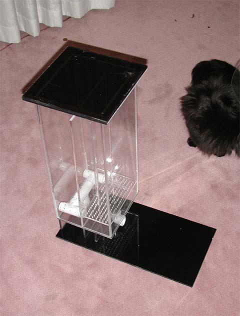
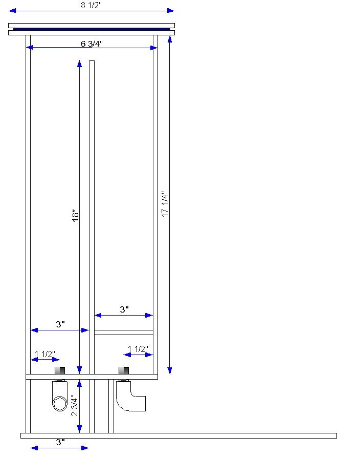
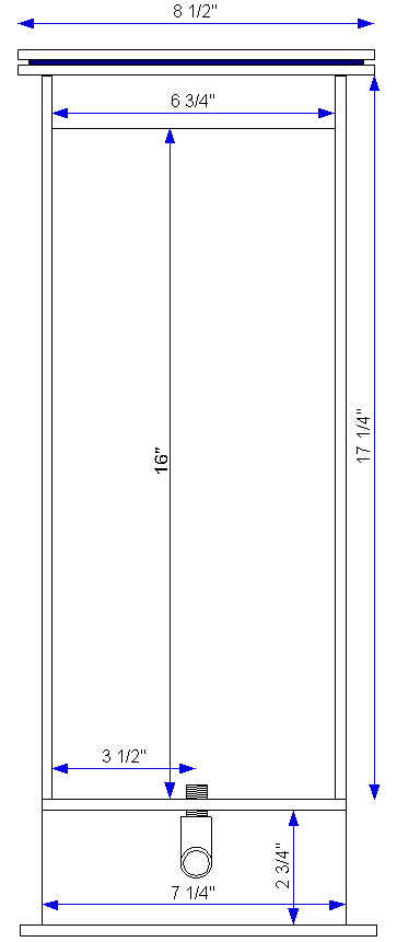
This will hold approx 1.9 gallons of media. I am guessing that one container of ARM is pretty close to a gallon. So it will hold more media in it than my old 24" high 6" diameter monstrosity reaction chamber did. All in a package that is under 17"(reaction chamber) in height. I was suprised at how much more volume that square shape holds than the cylinder. Do keep in mind that the sides of this reactor are 6.75" and not 6".
This reactor cost me under $30 for the acrylic to make it. But that is using cut offs at the local supply store. That is only using 1/2 of the acrylic I bought. I had enough pieces left to make the reaction chamber for one more. Plus purchase the pieces for a top and base(about $1 per piece in the cutoff bin). I was paying much more per foot for 6" diameter round stuff before this... I don't know why I didn't try this earlier!
Building a reactor is quite easy if you have the equipment to make all the cuts. Even without the saws etc you can still do it. Most plastics shops will do cuts for a price. Once you build one and get the idea the next one is a piece of cake. Some will say no but I think they are easy to build.
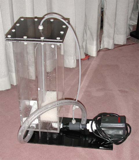
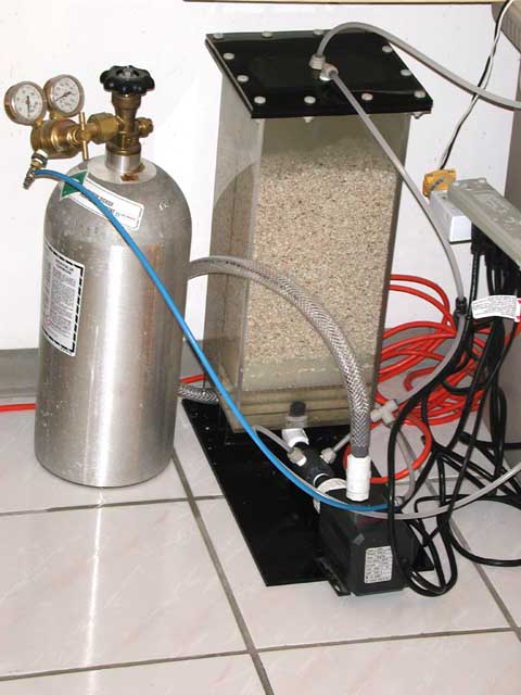
It took two containers of ARM to fill it(more than my 6" dia. monster I had built previously). The little venturi I built for the recirc/CO2 injection into the circulation pump is working fabulously! This reactor is a winner. The flow inside is great. Below is a picture of it running on my tub of LR. Well worth the effort, that is for sure. I'd say less than it was making a round one. But when you don't have a shop for making round flanges etc. Square is sure easy to do if you can get your hands on a table saw.
I use a minijet to feed tank water to the reactor. I placed a 1/4" irrigation valve immediately after the pump to control the drip rate.
All I had to do is set the flow rate, then once that is stable I set the bubble rate to about 30 per min. Then measure the alk. Once I get the alkalinity set to the levels I want by adjusting the bubble rate I then measure the pH of the effluent. Then all I use is a pH monitor to make sure nothing is changing.
Notes after 6 weeks: Running it at about 80 ml/min and 15-18 BPM. Effluent is at pH6.9 and dKh of 24. Seems the venturi for the intake of water and the recirc line is working great. Better than I expected actually. I took the BPM up to about 30 and it dropped my pH to 6.5 in short order.
I have been doing some thinking on why there is such a drastic difference between my design and a standard Ca reactor. Two things I think:
- The first is the spray bar. By having the water forced into the media through several small outlets instead of one large one as most reactors have it is massively increasing the surface area contact between the CO2 laden water and the media. (don't quote me on that but it sure seems logical and reasonable)
- The second is that by first forcing the water up through the media and then having an open area at the top any excess CO2 still in bubble form collects there to be re-introduced into the pump via the recirc line. Minimizing actual micro bubbles of CO2 leaving the reactor before having a chance to touch the media. The second half of the reactor aids in this by having the water again turn down and it is only after this second area of media that I remove the effluent. In effect I have created two zones in my reactor. A "dual stage" reactor within one chamber, in effect. The first is where the primary contact with the CO2 is done and the second is where any remaining CO2 is used up. With a recirc loop in between.
Construction
|
Acronyms for each fitting: FPT - Female Pipe thread. Threads are on the inside of the PVC. Slip - Standard slip fitting. No threads at all. MPT - Male Pipe Thread. Threads on the outside of the PVC. MPT goes into FPT.. you can attach FPT to FPT fittings with a nipple Those three are all dealing with PVC. As well I mentioned a nipple fitting. That is a small piece(depending on how long you need it) that is entirely made up of (or just the ends if long enough) MPT. It looks like a tube that is threaded on the outside. A John Guest fitting is a fitting that allows you to just plug in a 1/4" line without having to thread it. Slips in and locks and seals. If you take a close look at the pictures you will see where the poly line goes into the reactor at various points there are small grey fittings that the lines go into. Those are John Guest fittings. |
After the acrylic reaction chamber is built -- where the PVC needed to go through the bottom pieces -- I tapped (threaded the acrylic) them and used MPT fittings to thread through them until the fitting was tight against the acrylic. Then put a FPT over the open thread which the spray bar is attached to on the outlet side. The intake side for the pump is a FPTxFPT 1/2" 90 degree elbow with a 1/2" nipple through the acrylic. To ensure a seal I ran a bead of Weld- On around the PVC. Where the PVC goes into the pump is a bit more complicated.
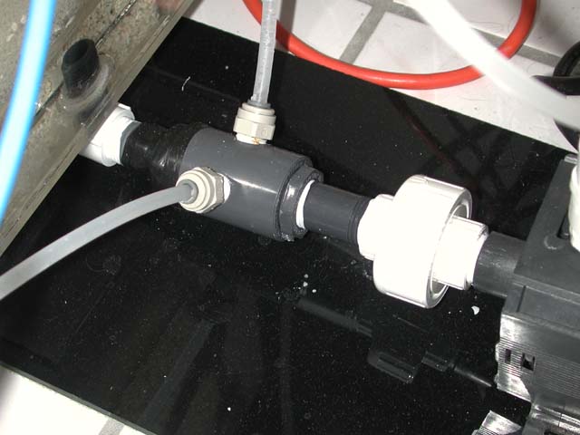
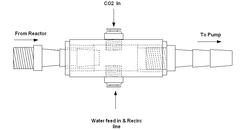
There is a threaded 90 in there. Into the 90 I put a 1/2" threaded barb. Onto this threaded barb I wrapped a rubber sealant tape around the barb. This taped end was threaded into a 1/2" FPTx 3/4" slipxFPT Sched 80 fitting. This was then slid into a 3/4" slipxslip fitting which has two 1/4" tapped holes for the CO2 intake/water in and the recirculation loop. Into the other side of the slipxslip fitting goes a second 1/2"FPTx3/4" slip fitting into which a 1/2" nipple goes in. Attched to that is a coupling which is threaded into the pump. Confusing huh? Below is a picture. I can't really explain it any better. Really. ;) What that whole last bit does is creates a venturi. A small one. But enough to ensure that there is suction going into the pump. This pulls water in from the recirc loop and also assists with the intake of water and CO2 to a small degree (I think).
As for construction order... here is a brief rundown:
Fit the bulkheads into the bottom, whatever you are using for bulkheads. Ensure they are in there properly so they won't leak.
Start by placing the sides of the reactor onto that base plate and bonding them as you go. This way you have the base plate to ensure a square fit. Let these dry for a while.
Then fit the spray bar onto the bulkhead that will be attached to the outlet of your circ pump.
Fit the inner baffle/divider into the reactor. glue it in place. Make the strainer plate so that it fist snugly inside and bond that in place. You should now have the shell and interior of the reactor completed.
Take a large piece of acrylic and start mounting the reactor supports to the reactor and then to this plate. The supports are the pieces I used to elevate the reactor so the fittings underneath are easy to access.
Once this is all done all you should have left is attaching the flange that glues to the reactor body.
That is it for the actual use of Weld-On.
If you take a look at the pictures on this page or in the very first few posts in the discussion thread you should get an idea of how I did it.
Diagrams
Side View
Front View
Venturi Fitting
Flow Diagram -- Where it says "recirculation in" will also be where the feed from the tank goes in. "Outlet" goes into the "Feed into Reactor" If you look at my pics you will see this.
Vinyl Tubing Explained: First set of tubing is for injecting water into the reactor from the tank. This is fed by a small pump like a mini jet or something like that into the intake of the recirculation pump. A second tube is used for the effluent returning to the tank. A third is for injecting CO2 into the reactor to decrease the pH of the reactor's water, this as well is injected into the intake of the recirculation pump so the CO2 is chooped up into finer bubbles. I have one extra tube running in mine. It is a recirculation loop that removes any excess CO2 collecting at the top of the reactor and reintroduces into the pump to be chopped up and put back into solution.
One additional step not included in these instructions nor the pictures:
Add a small square piece of acrylic to the top lid of the reactor, tapping it with the two JGF. By adding this piece, any air trapped under the reactor lid will accummulate in this smaller area, and be sucked out through the fittings.
How to start up a Calcium Reactor from scratch:
- Fill it with water. Hey some people don't .. really .
- Fill it as full as you can with a cup or something. Close the top up. Open up one of the fittings on top to bleed off excess air until all of it (or as much as possible is out). Use the feed pump to do this.
- Seal off and start up recirc pump. Let it run for a while with the feed pump running as well. Set the effluent rate at about 100ml/min.
- Once you have a steady flow rate and are satisfied all is fine(no leaks etc). Turn on the CO2. Aim for 60 BPM to start. Let it run over night.
- Measure effluent alk. I aim for double what I want in my tank to start. ie 24 dKH or there abouts. Once it has settled in at the alk you want after a day or so(possibly as fast as a few hours).
- Measure pH of effluent. Record this number.
- Over the next few days monitor tank's alk and Ca. If they drop increase the bubble rate. This will decrease the pH of the effluent and will increase its effectiveness at keeping your levels higher.
- Adjust the flow rates and CO2 rates as necessary. Repeat.
Remember this: Increasing flow rate increases pH. Increasing bubbles decreases pH. I usually aim for 6.8 to 7.0 to start and go from there.
Comments about the size of the reactor: Media is one part of the equation. Another to think about is total water volume. When you start running a high demand system or volume to be able to meet the demands you will need to replace what is taken away. In a high volume system you are going to need to have a higher volume output out of a reactor than say a reactor for a 30 gallon system. When you look at the amount a reactor generally runs for a smaller system you can expect ~ 100 ml per minute to be able to keep up to the demand (as the size of the tank's volume in comparison to the turnover through the reactor isnt too bad). But if you were to try and run 100 ml/min on say a 300 gallon tank you'd not be able to keep up with the demand. in a 30 gallon system 100ml/min is about .9% turnover per minute. In a 300 gallon system 100 ml/min is .09% or ten times lower. With ten times the tank volume you aren't going to be able to work it.
Now where I was going with this is that to meet this higher need to achieve those results as far as effluent rate you are going to not only need more media but more water volume as you are going to be turning over the volume of the reactor at a much faster rate. By this I mean to achieve the same percentage turnover that meets a 30 gallon tanks demands you are most likely going to need a similar rate(most likely less but) for a similarly stocked tank(how full it is not how many corals it has total). To get that percentage of what is needed you are going to be pushing a higher flow rate through. It may not need to be ten times as high but it will most likely be higher. And so you aren't pushing a ton of unused CO2 into the tank you'll want to have a smiliarly larger reactor volume so that the CO2 has time to be consumed.
For a while you will be able to just keep boosting the CO2 rate and flow rate. But after a while it will be counterproductive by increasing the amount of CO2 entering the system.
In a nutshell-- to meet the needs of a larger system media is one thing you will need more of, reactor water volume is another.
Is it worth it? If you are running a system that has a high Ca demand like I have in the past these reactors are worth thier weight in gold in my opinion and in my experience. Have you ever tried to dose two part solutions for a fully stocked tank? If you have, you'll understand why this is such a time saver and money saver! It costs me about $20 to fill my 10lb CO2 tank a year, maybe. Less now with this reactor I am betting. That $20 wouldn't even have gotten me one month's worth of additives for dosing. The build cost of this reactor for all my acrylic was around $35-45. I bought off cuts (or drop). Total outlay for this reactor... and additional equipment? Umm say $300CDN. To automate my system with this piece of equipment so I can leave it run on it's own.. I can't calculate how valuable that is.
The CO2 decreases the pH in the reactor to a level that the Calcium Carbonate based media breaks down and dissolves into solution for use in your tank. Basically to replace what is used by corals and other creatures and plants to grow and thrive.
After a few months of operation, a few more comments:
Well after having my feed and return lines continually blocked by algae growth. I took the advice listed elsewhere in this thread and wrapped the lines in heat shrink tubing. Works great. Nice Red colour too. Hasn't blocked up or had any growth problems since.
Another slight change I made was running the CO2 on its own into the venturi with the Recirc loop running into the other input on the venturi and the feed pump T'd into the recirc line.
Still running a very low bubble rate. Somewhere about 15-20. Don't really pay attention to it right now. Setting up my new tank. Getting good coralline growth in the tub. Hopefully it continues in the new tank.
Over the last number of months I have noticed that my CO2 rated had to be slowly increased to keep my pH at the level I like. Turns out a check valve that I had after my bubble counter had become slowly blocked, thus not allowing CO2 to pass. Put a new one in two days ago. I am now back at ~15 BPM or so and the pH is back at 7.0. So word to the wise.. keep an eye on those check valves. Even the ones not dealing with water.
The upflow side of the reactor uses up media more quickly than the downside. By moving the divider slightly to increase the size of the upflow side (thus decreasing the downflow side), the media should be consumed more equally.
Costs? These are estimates:
$35 for the acrylic. (scrap bin cutoffs as I said)
$15 for PVC fittings.
$80 for pump(orignally MAG 3 I traded for an EHEIM1250)
$20 for misc John Guest fittings, glue etc.
Also needed: 10g CO2 tank, Regulator, Needle Valve, ARM media, Vinyl Tubing.
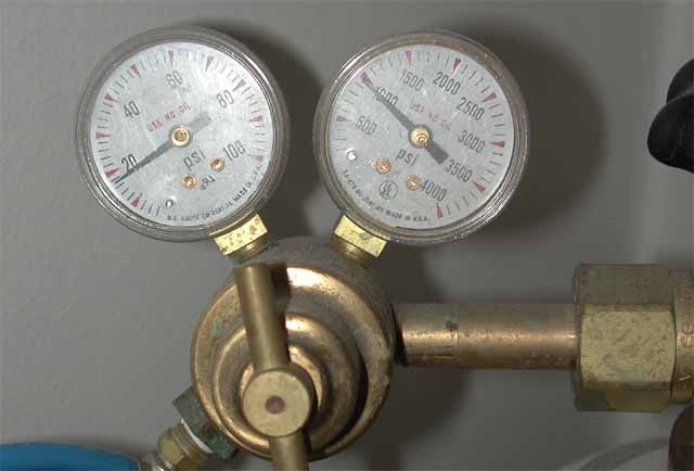
Darren's CO2 gauges
I found ReeferMadness.com has a gauge with solenoid, to shut off CO2 in the event of power failure.
Send a PM to DJ88 on Reef Central